Showing posts with label Phy n mech. Show all posts

Saturday, 22 February 2014

Big leap for fusion: more energy produced than spent igniting fuel

Researchers in the US have overcome a key barrier to making nuclear fusion reactors a reality. In results published in Nature, scientists have shown that they can now produce more energy than put into igniting fuel, at least on an experimental scale. The use of fusion as a source of energy remains a long way off, but the latest development is an important step toward that goal.
Nuclear fusion is the process that powers the Sun and billions of other stars in the Universe. If mastered, it could provide an unlimited source of clean energy because the raw materials are plentiful and the operation produces no carbon emissions.
During the fusion process, smaller atoms fuse into larger ones, releasing huge amounts of energy. To achieve this on Earth, scientists have to create conditions similar to those at the center of the Sun, which involves creating very high pressures and temperatures.
There are two ways to achieve this: one uses lasers and is called inertial confinement fusion (ICF), another deploys magnets and is called magnetic confinement fusion (MCF). Omar Hurricane and colleagues at the Lawrence Livermore National Laboratory opted for ICF, with the help of 192 high-energy lasers at the National Ignition Facility in the US, which was designed specifically to boost fusion research.
A typical fusion reaction at the facility takes weeks of preparation. But the reaction is completed in an instant (150 picoseconds, to be precise, which is less than a billionth of a second). In that moment, at the core of the reaction, the pressure is 150 billion times atmospheric pressure. The density and temperature of the plasma created is nearly three times that at the center of the Sun.
The most critical part of the reaction, and one that had been a real concern for Hurricane’s team, is the shape of the fuel capsule. The capsule is made from a polymer and is about 2mm in diameter (about the size of a pinhead). On the inside it is coated with deuterium and tritium—isotopes of hydrogen—that are frozen to a solid state.

This capsule is placed inside a gold cylinder, when the 192 lasers are fired, they hit the capsule and indirectly cause a fusion reaction. The lasers hit the gold container, which emit X-rays that heat the pellet and make it implode, causing a fusion reaction. According to Debbie Callahan, a co-author of the study: “When the lasers are fired, the capsule is compressed 35 times. That is like compressing a basketball to the size of a pea.”
The compression produces immense pressure and temperature, leading to a fusion reaction. Problems with the process were overcome last September, when, for the first time, Hurricane was able to produce more energy output from a fusion reaction than the lasers put into it. Since then, he has been able to repeat the experiment.
Hurricane’s current output, although more than the hydrogen fuel put into the reaction, hasn’t yet reached the stated goal to achieve “ignition," where nuclear fusion generates as much energy as the lasers supply. At that point it might be possible to make a sustainable power plant based on the technology.
In plasma physics, the energy produced by a fusion reaction increases exponentially with the pressure applied to the system. According to Hurricane, they only need to double the pressure to achieve ignition. His other achievement is that, with these experiments, he has been able to show that computer simulations can predict experimental results.
Scientists have been trying to tame fusion power for more than 50 years with little success. Although the National Ignition Facility, a $3.5-billion operation, was built for classified government research, half of its laser time was devoted to fusion with an aim to accelerate research. Zulfikar Najmudin, a plasma physicist at Imperial College, said: “These results will come as a huge relief to scientists at NIF, who were very sure they could have achieved this a few years ago.”
With laser-mediated ICF showing positive results, the obvious question is how does it compare with magnet-mediated fusion? According to Stephen Cowley, director of Culham Centre for Fusion Energy, there isn’t a precise way of comparing the two technologies. But if a comparison has to be made, MCF still is ahead of ICF because a 1997 experiment by the European fusion leaders Joint European Torus achieved near break-even when they produced 16MW (megawatt) of energy for 24MW of input.
“We have waited 60 years to get close to controlled fusion. We are now close in both magnetic and inertial. The engineering milestone is when the whole plant produces more energy than it consumes,” Cowley said. That may happen at the fusion reactor ITER, under construction in France, which is expected to be the first power plant that produces more energy than it consumes to sustain a fusion reaction.The Conversation
Nature, 2014. DOI: 10.1038/nature13008  (About DOIs).
This article was originally published on The Conversation.

Is it time to move away from silicon-based solar?


CHICAGO—Currently, the world has the capacity to manufacture over 40 Gigawatts of solar panels each year, the vast majority of them silicon-based. And it's easy to see why: our expertise with processing the material has led to a staggering drop in costs, making photovoltaics (PVs) much more cost-competitive than just about anyone had predicted.
But that manufacturing innovation hasn't been matched on the basic research side; it's been over a decade since the last time anyone set a new efficiency record for silicon cells. And, even as manufacturing costs have dropped, the cost of support equipment and installation has remained stubbornly high and is an ever-increasing slice of the total price of PV systems.
That's got people thinking that it might be time that we get more power out of each installation. At the meeting of the American Association for the Advancement of Science, two researchers spelled out how they were finding ways to take an expensive material and make it cheap enough to be deployed on the same scale as silicon.
The material in question is gallium arsenide, which can be fashioned into solar cells with efficiencies twice those of silicon. The high cost of the material, however, has limited its use to applications like satellites. But two research groups have come up with ways to get much more out of GaAs.

Gallium goes thin

Both teams have figured out how to make extremely thin layers of GaAs. Harry Atwater's group at Caltech has developed a process that allows them to peel hundreds of thin layers off a large aggregate of the material, much like individual graphene sheets can be peeled off a block of graphite. The end result is an extremely thin film of GaAs (he passed some samples around to the audience).
John Rodgers, who works at the University of Illinois at Urbana-Champaign, grows thin layers of GaAs separated by a thin sacrificial layer. When the sacrificial layer is etched away, you're left with a collection of thin GaAs chips; the silicon wafer they were grown on can then be recycled, cutting down on the costs significantly. A plastic stamp can then pick up the chips and "print" them onto just about any surface, including one pre-patterned with wiring.
In the rare cases where GaAs chips are used here on Earth, they're typically used in what's called a concentrated solar system, where lenses pump as many photons into the chips as they can manage without melting. But these tracking and focusing systems add significantly to the cost of these systems. Both groups are thinking of doing some focusing, but going about it in different ways.
Rodgers, who can print large arrays of tiny GaAs chips, is managing costs by keeping things simple: his team's process simply involves dropping a plastic sphere that acts as a lens on top of the chip. There are some ideas about how to manufacture more specialized spheres that focus the light more efficiently, but, for now, simplicity is the selling point.

Trapping the photons

Caltech's Atwater is making the focusing device a more central part of his system for reasons that focused on the physics of what happens inside the chips. When a photon is absorbed, it creates a free electron and a positively charged "hole." There are three things that can happen to this pair. One is that they end up at electrodes, producing a useful current. One is that they recombine uselessly, releasing the energy as heat. The third is that they recombine by releasing another photon.
For Atwater, the key to an efficient photovoltaic material is minimizing the wasteful recombination of electrons and holes. And that means getting them to re-emit a photon—in his view, a good photovoltaic material is also a good LED. In these materials, photons get absorbed and re-emitted a hundred times before being productively harvested, and the inside of the material is a sea of photons.
The danger here is that some of the photons escape back out of the material. To limit that, the GaAs can be put on a reflective backing that sends the stray photons right back into the chip. The front has to let sunlight in, but then keep photons from escaping. To do that, he's testing a system that looks a bit like two U's with their bottoms fused (technically, it's back-to-back parabolic lenses connected by a narrow aperture). This takes photons from a broad area and funnels them into the PV chip. The other end of the U acts like a reflective cap, making it very hard for a photon to escape from the chip without being reflected back into it.

Grab all the wavelengths

At this point, we're pumping lots of photons into the GaAs device and keeping them there until they're absorbed. The next way to up the efficiency is to have multiple independent photovoltaic devices, each tuned to different wavelengths. Traditionally, this has been done with layered devices, where each layer takes out a specific chunk of the spectrum.
And that's what Rodgers' team is already doing, by placing a standard triple-junction cell (which absorbs three different chunks of the spectrum) on top of a fourth cell that grabs yet another chunk. Atwater hopes to use the optic devices his team is working on to split the light into colors and direct them to independent photovoltaic devices.
Both of these faculty members have started companies to try to commercialize their work, and the devices they're making are already above the 40-percent efficiency mark—double that of silicon cells. Rodgers' company already has a 5MW capacity plant, and he said that scaling up production to an 80MW capacity plant would let them produce devices that are cost-competitive with coal.
Lots of great sounding technologies never make it past the demonstration phase, or they get caught up in market forces beyond their developers' control. But in this case, market forces are clearly working in the devices' favor. As installation costs become an ever larger fraction of the total cost of a solar installation, it's clear that getting more out of each installation is likely to be critical.

Saturday, 16 November 2013

Metal to Plastic: Design Flexibility


 Even though metal-to-plastic conversion has been around since the 1950s, many manufacturers are still not familiar with all the benefits it provides.
Automotive and aerospace companies have been most active in converting existing metal products or parts to plastic, driven by the need to reduce weight and improve fuel efficiency. With proper design, engineered plastics can be just as strong as metal. They can also be more chemical-resistant with exceptional heat resistance, making them good choices for fuel systems, fluid handling systems, and other high-temperature applications. Plastics that are engineered to be thermally and electrically conductive can be used as EMI/RFI shields, or in automotive electronics.
Benefits that conversion to plastic can provide are:

  • High tensile strength with proper structural design
  • Reduced part weight
  • Highly repeatable in processing (less scrap)
  • Lower manufacturing costs
  • Enhanced regulatory compliance
  • Greater design flexibility (part consolidation)
  • Lower packaging and shipping costs
  • Up to six times longer tool life.
Current metal-to-plastic trends focus on reducing weight, improving strength and corrosion resistance, and consolidating multiple metal parts into one plastic part. Plastic parts can be just as tough as metal parts and achieve the same tight tolerances, with fewer secondary operations. In general, companies can expect to achieve an overall cost savings of 25% to 50% by converting to plastic parts
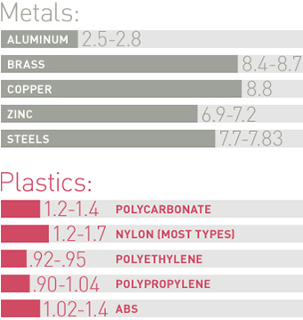
A comparison of the specific gravity values of metals to plastics


shows how dramatic the difference in weight can be.


Design Freedom

Converting to plastic parts gives manufacturers more freedom in product design, including greater variety in material selection and being able to create more complex geometries. It is much easier to produce complex shapes out of plastic than metal, due to injection molds allowing for under-cuts, threads, ports, and tight tolerances allowing a net shape to be produced to the finish level specifications.
“Plastics can be made to flow to produce thin-walled parts with uniform wall dimensions, replacing the more costly thicker-walled design features of most die-cast metal parts,” says Ken Glassen, vice president of engineering for Kaysun Corporation, an injection molder in Manitowoc, WI. “Multiple metal parts can be replaced by one injection-molded part made of tough engineered plastic, eliminating the need for fasteners and assembly.”
Plastic parts can actually be stronger than metal parts by using engineering-grade materials with proper structural design. The ability to mold in features for structural strength such as ribs, bosses, and gussets when the part is originally produced (instead of fastening, welding, and gluing afterwards) can increase the total strength of the assembled part as well as reduce additional costs.
“There are many more options available for materials and additives/fillers when using plastic instead of metal,” adds Glassen. “Converting from metal to plastic gives designers the ability to produce final net shape and dimensions, all in one process.”

Material Selection

Polymer science has advanced to the point where vendors can compound a variety of plastic materials with specific fillers and reinforcements that provide a tremendous amount of structural integrity. Plastic can be as strong as metal with proper material selection paired with design optimization, and weigh far less.
Choosing the right plastic can take some time, depending on the project. One of the greatest advantages of plastics is the availability of more than 25,000 engineered materials for manufacturing applications. New, higher-performance blends and hybrids can also be custom-designed to meet very specific performance requirements.
Key considerations for type of plastic are:

  • Crystalline vs. amorphous: evaluate requirements such as chemical resistance, impact, flow, processing, etc.
  • Additives: additives will affect strength, stiffness, temperature performance, appearance, package requirements, and cost.
  • Carbon and stainless steel fillers improve conductive and/or shielding properties.
  • Lubricant fillers improve wear and friction properties.
  • Mineral fillers improve electrical performance, weighted feel, sound dampening, and higher specific gravity and improve dimensional stability.
  • Impact modifiers improve toughness.

Making the Switch

The first step is finding out if the project is suitable for metal-to-plastic conversion. This requires considerable analysis and is not necessarily a quick determination. It is essential to fully understand the end-use application, environmental conditions, material evaluations and analysis, manufacturability, and economic feasibility. The design engineers must be able to accurately evaluate the real-world environment that will impact the product, including chemical exposure or contact solutions, temperature ranges, shielding, and forces (including worst-case scenarios). All this information must be analyzed together to make the best material choice.
“With plastic, you can prove it out using finite element analysis before ever molding a part and investing in tooling,” says Glassen. “With analysis of the entire system up front (system loads, temperatures, chemicals, and UV considerations), you can be sure that plastic is the right choice for your application.”

Thursday, 14 November 2013

Nano Advancement Repels Liquids


Staying dry is easy when water’s the only worry. Super hydrophobic surfaces crop up everywhere in nature. Thanks to a relatively high surface tension, water beads up and rolls right off broccoli, cabbage, euphorbia, duck feathers, butterfly wings, and mosquito legs. Humans, too, have managed to manufacture their own water-repellent materials.
But keeping dry when oil, alcohol, or other liquids are involved as well is a different story. These other liquids have a lower surface tension, which is why oil spreads on Teflon while water skits across it (in fact, in some cases, super hydrophobic surfaces are like sponges for other liquids, which is a why oil spills kill ducks).

Detail of the superomniphobic surface developed by Professor Anish Tuteja and his team that highlights the hierarchical texture present with the surface texture. Image: University of Michigan


But now thanks to a new nano technique, researchers in the Department of Materials Science and Engineering at the University of Michigan have come up with a material that repels water, oil, alcohol, and just about any liquid under the sun.
“The key is, essentially, trapping as much air as you can underneath the liquid droplet,” says Anish Tuteja, an assistant professor at the University who spearheaded the project. Drops of liquid naturally turn spherical when unencumbered by surfaces. To keep them round and rolling off, a surface needs to be as un-surface-like as possible. “Imagine a net,” says Tuteja. “The openings are the air pockets, and if the liquid is the tennis ball, it can’t penetrate through it.”

Hierarchical Approach

Tuteja sought to make those openings as large as possible without letting the ball pass through, which, in the case of liquids, would mean wetting the surface. His fabric needed to “maximize the fraction of air, while maintaining enough breakthrough pressure.” The geometry of the fabric is “reentrant,” which is to say it bends back on itself, like a sphere. Tuteja showed, back in 2007, that such shapes cause low surface tension liquids to bead up. So the new textile has cylindrical fibers.

A series of images illustrating droplets of acetic acid bouncing on the hierarchically structured superomniphobic surface that is tilted by 2° relative to the horizontal. Image: University of Michigan

To make it truly repellent to all liquids, Tuteja used a hierarchical approach. Onto the re-entrant mesh of suitable porosity, Tuteja sprayed a coating of tiny reentrant particles of suitable porosity. It’s just an “aggregate of spheres,” says Tuteja of the coating.
The result is a surface that keeps the fluids hopping—off.
 

Nearly all of them, that is. The “just about” in “just about any liquid under the sun,” found above, comes thanks to some chlorofluorocarbons of extremely low surface tension who had to spoil the party. Aside from them, every liquid Tuteja and his colleauges threw at the new surface bounced right off.

Potential Applications

One measure of how un-wetable a material is it’s surface energy. Teflon has a score of 17 millinewtons a meter. Tuteja’s new surface has a 10. That’s a good 60% to 70% lower than the famous non-stick stuff. And where Teflon is unwieldy to process—it’s hard and won’t dissolve into solvents—this slick new material is a breeze. It can be sprayed on and dissolves easily into several solvents. It’s toxicity, however, has yet to be tested.

The potential applications are many, as evidenced by the slew of calls from industry Tuteja has received. These include textile manufacturers and shoe manufacturers looking to make their products stain free and engine manufacturers and people involved in wastewater treatment looking to avoid buildup. Ship builders, hoping to cut down on drag, want to cover their hulls in the stuff. Manufactures of smart phones and tablets see a way to keep their screens free of fingerprints and other smudge. Those who make sunglasses and goggles look forward to a future with fog and filth free lenses.

None of that is to say that Tuteja is in it for the money. “I’d like to see it get out there, whether I make five dollars or a thousand,” he says. “The fun part is doing the work.”

Sunday, 3 November 2013

Breakthrough research produces brighter, more efficiently produced lighting % Bright, laser-based lighting devices.

Breakthrough research produces brighter, more efficiently produced lighting
This illustration demonstrates how bright blue LED light, shone through its complementary yellow phosphor, yields white light. Credit: UCSB


By determining simple guidelines, researchers at UC Santa Barbara's Solid State Lighting & Energy Center (SSLEC) have made it possible to optimize phosphors –– a key component in white LED lighting –– allowing for brighter, more efficient lights.
"These guidelines should permit the discovery of new and improved phosphors in a rational rather than trial-and-error manner," said Ram Seshadri, a professor in the university's Department of Materials as well as in its Department of Chemistry and Biochemistry, of the breakthrough contribution to solid-state lighting research. The results of this research, performed jointly with materials professor Steven DenBaars and postdoctoral associate researcher Jakoah Brgoch, appear in The Journal of Physical Chemistry.
LED (light-emitting diode) lighting has been a major topic of research due to the many benefits it offers over traditional incandescent or fluorescent lighting. LEDs use less energy, emit less heat, last longer and are less hazardous to the environment than traditional lighting. Already utilized in devices such as street lighting and televisions, LED technology is becoming more popular as it becomes more versatile and brighter.
According to Seshadri, all of the recent advances in solid-state lighting have come from devices based on gallium nitride LEDs, a technology that is largely credited to UCSB materials professor Shuji Nakamura, who invented the first high-brightness blue LED. In solid-state white lighting technology, phosphors are applied to the LED chip in such a way that the photons from the blue gallium nitride LED pass through the phosphor, which converts and mixes the blue light into the green-yellow-orange range of light. When combined evenly with the blue, the green-yellow-orange light yields white light.
The notion of multiple colors creating white may seem counterintuitive. With reflective pigments, mixing blue and yellow yields green; however, with emissive light, mixing such complementary colors yields white.
Art to science
Until recently, the preparation of phosphor materials was more an art than a science, based on finding crystal structures that act as hosts to activator ions, which convert the higher-energy blue light to lower-energy yellow/orange light.
"So far, there has been no complete understanding of what make some phosphors efficient and others not," Seshadri said. "In the wrong hosts, some of the photons are wasted as heat, and an important question is: How do we select the right hosts?"
As LEDs become brighter, for example a they are used in vehicle front lights, they also tend to get warmer, and, inevitably, this impacts phosphor properties adversely.
"Very few phosphor materials retain their efficiency at elevated temperatures," Brgoch said. "There is little understanding of how to choose the host structure for a given activator ion such that the phosphor is efficient, and such that the phosphor efficiency is retained at elevated temperatures."
However, using calculations based on density functional theory, which was developed by UCSB professor and 1998 Nobel Laureate Walter Kohn, the researchers have determined that the rigidity of the crystalline host structure is a key factor in the efficiency of phosphors: The better phosphors possess a highly rigid structure. Furthermore, indicators of structural rigidity can be computed using density functional theory, allowing materials to be screened before they are prepared and tested.
This breakthrough puts efforts for high-efficiency, high-brightness, solid-state lighting on a fast track. Lower-efficiency incandescent and fluorescent bulbs –– which use relatively more energy to produce light –– could become antiquated fixtures of the past.
"Our target is to get to 90 percent efficiency, or 300 lumens per watt," said DenBaars, who also is a professor of electrical and computer engineering and co-director of the SSLEC. Current incandescent light bulbs, by comparison, are at roughly 5 percent efficiency, and fluorescent lamps are a little more efficient at about 20 percent.
"We have already demonstrated up to 60 percent efficiency in lab demos," DenBaars said.

Bright, laser-based lighting devices


Bright, laser-based lighting devices
This is a photograph of bright white light (right) achieved using lasers in combination with phosphors next to an image of the phosphor with no illumination. Credit: K.Denault/UCSB

As a modern culture, we crave artificial white lights—the brighter the better, and ideally using less energy than ever before. To meet the ever-escalating demand for more lighting in more places and to improve the bulbs used in sports stadiums, car headlights and street lamps, scientists are scrambling to create better light-emitting diodes (LEDs)—solid state lighting devices that are more energy efficient than conventional incandescent or fluorescent light sources.
Just one thing stands in the way: "droop," the term for a scientific problem related to LEDs currently in use. Droop refers to the fact that LED efficiency falls as operating currents rise, making the lights too hot to power in large-scale applications. Many scientists are working on new methods for modifying LEDs and making progress toward cooler, bigger and brighter bulbs.
Now investigators at University of California, Santa Barbara, led by material scientists Kristin A. Denault and Michael Cantore, have devised an alternative means of creating high-power white light by using a different excitation source—a laser diode in combination with inorganic phosphors, instead of the traditional LEDs.
Their laser-based lighting options are high in efficiency and high in performance metrics, according to their study, which is described in the journal AIP Advances, which is produced by AIP Publishing.
"We found two ways to create high-intensity 'cool' white light, explained Denault. "In one we used a blue laser diode and yellow-emitting phosphor powder with a luminous flux of 252 lumens, which is comparable to current high-brightness white LEDs. For our second method, we used a near-ultra-violet laser diode and a combination of red-, green-, and blue-emitting phosphors."
They also achieved a variety of other color temperatures with high color rendition, broadening the range of applications for these new lights, she said.

Saturday, 2 November 2013

Better Joints : Better Mechanisms.


Compliant materials with a strong impact
The recent Empa spin-off Monolitix AG specializes in compliant mechanisms. These are friction-less and wear-free and are also lighter, more hygienic and cheaper than conventional joint mechanisms. They have an enormous range of potential applications in the most diverse fields. The new company's young entrepreneurs are now setting about breaking into the market with their first products.
We are surrounded by objects with joints from morning till night. "We come across them in a thousand different forms", explains Flavio Campanile, aeronautical engineer and Chairman of the Board of Directors at the Empa spin-off Monolitix. "Without joints, everything would be rigid: you would not able to steer a car and the brakes on bicycles would not work." The "trick" is that rather than using conventional bearings and joints to create the required movement for a mechanism, these so-called solid-state mechanisms deliberately dispense with these types of elements. Instead, the material is deformed in a controlled and reversible way. As a figurative example, instead of a pair of pliers made from several parts, as representative of the traditional joint principle, Campanile highlights a pair of tweezers made from a single, elastically deformable component.
Monolithic systems with many advantages
"The advantages of monolithic systems are obvious" explains Campanile: joint-free mechanisms are friction-less and wear-free and therefore also maintenance-free. This can drastically reduce the running costs of machines and instruments. In areas where high standards of hygiene are required, such as in medical devices or in the food industry, they are advantageous because they are easier to clean and sterilize. In addition, with solid-state mechanisms, assembly costs can be reduced dramatically or even avoided altogether. This leads to much cheaper production processes.

Compliant materials with a strong impact
A conventional joint construction (left) has a very simple design. A monolithic solution (right) has a more complex design, but has many advantages in operation.
And finally, compliant mechanisms can also perform functions that would be inconceivable with conventional systems: for example, aircraft wings which constantly change their geometry - like those found in nature - and optimise their use of the aerodynamic forces. Another possibility is rear spoilers for Formula 1 racing cars which generate more down force with the same air resistance, thus enabling the car to travel faster through corners. Compliant concepts are also extremely well-suited to rotor blades on wind turbines that are difficult to access or for anti-friction and friction bearings in solar power plants, which are subjected to mud, sand or dust and have to function under extreme conditions.
The business idea began to take shape when Campanile's doctoral students at the Federal Institute of Technology (ETH) Zurich, René Jähne and Alexander Hasse, began working in this field. The first prototypes for medical technology were created in the course of their dissertations. This is how the ideas came to life. For many years, the team of three carried out their research at the Empa laboratory "Mechanics for Modelling and Simulation", during which time they developed techniques for analyzing flexible elements and their deformation as well as algorithms for shape optimization. Their results were then incorporated into software modules, databases and patents. The time to establish their own company came in 2010.
Gripping systems from the catalogue and innovative ideas from the custom manufacturing team
Compliant materials with a strong impact
A range of robotic grippers from Monolitix is already available to mechanical engineers. They are extremely light, free of play and friction less.

Even before they joined glaTec, Empa's business start-up center in Dübendorf, they acquired their first customer: baked-goods manufacturer HUG uses their robotic grippers to take small pastry cases carefully, quickly and hygienically off the production line and put them into their packaging. The task for Campanile and his colleagues is now to inspire new customers with their many ideas and to persuade them to develop new products together. The Head of Product Development at Monolitix, René Jähne, explains: "As a small company, it would be too expensive for us to develop and market complex products for a specific market single-handedly." The company does offer a small, but refined range of gripping systems in its catalog. However, an approach that he believes will be far more successful is to actively approach manufacturers of machine components, tools and instruments. According to Jähne, "In this way, with every project, we become better acquainted with the needs of individual partners and their markets." During the discussions, clients in return gain an insight into the engineering work carried out at Monolitix. It is quickly becoming clear that the design for a compliant system can ultimately only be created with a multidisciplinary approach and a lot of expertise.
Demand for the new technology is strong, as the company's founders are proud to note, also referring to the fact that Monolitix is already financially independent. This is quite unusual for such a young company. According to the business plan, Monolitix should grow into an SME with around 40 employees within the next five years. 

Monday, 28 October 2013

Successful test of new US magnet puts Large Hadron Collider on track for major upgrade

The U.S. LHC Accelerator Research Program (LARP) has successfully tested a powerful superconducting quadrupole magnet that will play a key role in developing a new beam focusing system for CERN's Large Hadron Collider (LHC). This advanced system, together with other major upgrades to be implemented over the next decade, will allow the LHC to produce 10 times more high-energy collisions than it was originally designed for.
Dubbed HQ02a, the latest in LARP's series of High-Field Quadrupole magnets is wound with cables of the brittle but high-performance superconductor niobium tin (Nb3Sn). Compared to the final-focus quadrupoles presently in place at the LHC, which are made with niobium titanium, HQ02a has a larger aperture and superconducting coils designed to operate at a higher magnetic field. In a recent test at the Fermi National Accelerator Laboratory (Fermilab), HQ02a achieved all its challenging objectives.
LARP is a collaboration among the U.S Department of Energy's Brookhaven National Laboratory (Brookhaven), Fermilab, Lawrence Berkeley National Laboratory (Berkeley Lab), and the SLAC National Accelerator Laboratory (SLAC), working in close partnership with CERN. LARP has also supported research at the University of Texas at Austin and Old Dominion University.
"Congratulation to all the LARP team for this brilliant result," said Lucio Rossi, leader of the High Luminosity LHC project at CERN. "The steady progress by LARP and the other DOE supported programs clearly shows the benefits of long-term investments to make serious advances in accelerator technology."
"In the context of the LARP magnet program, this marks the end of the R&D phase and the beginning of the focused development of the magnets that will be installed for the LHC luminosity upgrade", said Eric Prebys of Fermilab who has served as director of LARP for the last five years. "However, the implications go well beyond that, in that it establishes modern niobium tin as a powerful superconductor for use in accelerator magnets. This success is a tribute to the skill, hard work, and collaborative spirit of all of the people involved."
Toward future physics at the LHC
Last year's discovery of the Higgs boson fulfilled one of the major goals of the LHC, arguably the most powerful and complex scientific instrument ever built. Yet precision measurements of the Higgs are still to be made, as well as explorations of new physics including supersymmetry, dark matter, extra dimensions, and other wonders. The LHC's present complement of Interaction Region Quadrupole magnets, which focus the beams toward the collision points inside the experiments, will reach performance limits well below what's required for this ambitious physics program. One of the primary goals of LARP is to support CERN's plan to replace these focusing magnets in about 10 years as part of the High Luminosity LHC project.
The number of useful physics events generated by a collider can be calculated from a parameter called integrated luminosity. For the past decade, CERN has anticipated a series of upgrades that will increase the LHC's integrated luminosity 10-fold – the goal of the High Luminosity LHC project, consistently recognized as a top priority for the worldwide particle physics program. This goal presents extraordinary challenges, requiring a global effort to push the state of the art in a number of critical technologies.
The most specific need is for more powerful magnets to focus the proton beams at the interaction points. Not only must the magnets produce a stronger field, they will also require a larger temperature margin and have to cope with the intense radiation, which comes hand in hand with the planned increase in the rate of energetic collisions. These requirements go beyond the capabilities of niobium titanium, the material on which all previous accelerator superconducting magnets have been based.
Modern niobium tin is an advanced superconducting material that can operate at a higher magnetic field and with a wider temperature margin than niobium titanium. Unfortunately, niobium tin is brittle and sensitive to strain – critical factors where intense electrical currents and strong magnetic fields create enormous forces as the magnets are energized.
Large forces can damage the fragile conductor or cause sudden displacements of the superconducting coils, releasing energy as heat and possibly resulting in a loss of the magnets' superconducting state, called a "quench." When combined temperature, field, and current density cross a critical boundary into ordinary conductivity, the enormous flood of electrons that previously rushed unimpeded through the superconductor slams into a wall of electrical resistance.
Accelerator magnets are designed to withstand these disruptive and potentially damaging events. Nevertheless, the ability to reach the operating level with few or no quenches is an essential performance requirement.
In order to address these challenges, LARP adopted a mechanical support structure based on a thick aluminum shell, pre-tensioned at room temperature using water-pressurized bladders and interference keys. This design concept, developed at Berkeley Lab under the DOE General Accelerator Development program, was compared to the traditional collar-based clamping system originally used in Fermilab's Tevatron and all subsequent high energy accelerators, and scaled-up to 4 m length in the LARP Long Racetrack and Long Quadrupoles. The HQ models further refined this mechanical design approach, in particular by incorporating full coil alignment.
LARP's HQ02a is designed like all LHC magnets to operate in superfluid helium at temperatures close to absolute zero. However, it has a larger beam aperture than the present focusing magnets – 120 millimeters in diameter compared to 70 millimeters – and the magnetic field in the superconducting coils that surround the magnet reaches 12 Tesla, 50 percent higher than the present 8 Tesla. The corresponding field gradient, the rate of increase of field strength over the aperture, is 170 Tesla per meter.
Another key objective of the HQ02a design is to minimize any deviations from the precise magnetic field patterns required to focus the beams at the interaction point, and to maintain this high field quality during ramping up to full magnetic field strength. To address these requirements, the LARP High-Field Quadrupole program incorporated a newly designed cable to minimize induced currents, plus precise alignment at all phases of coil fabrication, assembly and magnetic excitation.
"The desired performance characteristics were clearly demonstrated by the test recently completed at Fermilab," says Berkeley Lab's GianLuca Sabbi, who directed the HQ02 development. "The magnet quickly achieved its design field gradient with low sensitivity to ramp-rate effects. This result was made possible by the expertise and dedication of many scientists, engineers, and technicians at all the collaborating laboratories."
As the last step in a decade-long progression of niobium-tin technology advancements by LARP, the sterling performance of HQ02a has reaffirmed the key design elements for focusing magnets that will meet the needs of CERN's High Luminosity upgrade.
"This is a major step forward in reaching our ultimate goals," said Bruce Strauss, LARP program manager at DOE's Office of Science. "It should not be regarded as a single accomplishment but rather the realization of a significant number of individual goals in the design, construction, and testing of Nb3Sn beam-line magnets."

Thursday, 5 September 2013

Random Physics Paradox Questions Part - 3 :-)

Question #1

A mass is suspended by two identical springs, which are connected in series as shown in the photograph at the left below from a fixed point. Each spring has a parallel string loosely connected from the upper and lower ends to the center as shown in the photograph at the right.

The coupling clip between the two springs can be disconnected such that the mass will then be supported from the fixed point by two parallel spring-string units, one with the spring on top and the string on the bottom, the other with the string on the top and the spring on the bottom.
When the series spring support is disassembled so that the mass is supported by two series spring-string combinations, where will the mass be relative to its initial position as shown in the figure above?
  • (a) The mass will be at a higher position.
  • (b) The mass will be at a lower position.
  • (c) The mass will be at the same vertical position.

Question #2

A (very light) styrofoam block with a (much heavier) aluminum block attached to its top surface, as seen in the photograph at the left below, is placed into a container of water. The combined blocks float with one-half of the styrofoam block immersed in the water, as seen in the photograph at the right below. It's a bit ratty looking, but it works.

Now remove the floating block combination from the water, turn it upside down, and replace it in the water with the aluminum block underneath the styrofoam block. The question is what will happen? Perhaps it might float higher out of the water, so that the black line on the foam block is above the level of the water. On the other hand, perhaps the aluminum block will pull the foam block further into the water, so that the water level will be above the black line, or the blocks may even sink! Or, perhaps it will float with the black line at the water level, as in the original case.
When the inverted block combination is placed in the water (with the styrofoam block on top) where will the water level be relative to the black line in the center of the styrofoam block?
  • (a) The black line will be above the water level.
  • (b) The black line will be at the water level, as in the original case.
  • (c) The black line will be below the water level.
  • (d) The blocks will sink.
Here is a second question for extra bonus credit: The water level of the container with the blocks in their original configuration is marked by the top of the black tape on both sides of the tank. After the blocks are inverted and replaced in the water, will the water level in the tank be higher, lower, or the same?

Question #3

The question for this week has a somewhat different format from the traditional multiple guess questions previously presented.
Shown below are the front and side views of a three-dimensional object. These drawings are complete and correct mechanical drawings for the object, such as those one might give to a machine shop for its construction. The object is not a solid sphere or a thin spherical shell, and it can be made in a machine shop, as we will see next week.

The question is, what is the third (top) view, and what is the object.
Rather than give you a selection of answers, we give you a selection of clues about the top view:
  • (a) It might be a circle.
  • (b) It might be a square.
  • (c) It might be a square with other lines.
  • (d) It might be a triangle.
  • (e) It might be a triangle with other lines.

Question #4

The question for this week is another in the format of last week's question, except this one may be a little easier.
Shown below are the front and side views of a three-dimensional object. These drawings are complete and correct mechanical drawings for the object, such as those one might give to a machine shop for its construction.

The question is, what is the third (top) view, and what is the object.
Rather than give you a selection of answers, we give you a selection of clues about the top view:
  • (a) It might be a circle.
  • (b) It might be two squares.
  • (c) It might be two squares with other lines.
  • (d) It might be two triangles.
  • (e) It might be two triangles with other lines.

Question #5

A rectangular frame with a spring hanging from its top segment weighs about 3.5 Newtons, as seen from the reading of the spring scale in the photograph at the left below. If you hang a 500 gram mass on the spring, how much will the scale read? Right! The mass weighs about 5 Newtons, so the scale will read about 8.5 Newtons, as seen in the center picture. Now if you extend the spring so that a small string loop can be connected between hooks on the bottom of the weight and the platform at the bottom of the frame, what will the spring scale read? Right! Its weight does not change, so the spring scale continues to read about 8.5 Newtons. All right, it's not perfect, but it is close enough for this demonstration.


Now suppose that you burn the string, so the mass is free from the constraint holding it to the bottom of the frame. What will the spring scale do instantaneously when the string releases?
The spring scale will:
  • (a) move to a higher value.
  • (b) move to a lower value.
  • (c) remain at the same value.

Question #6

A small hand-cranked generator known as a "Genecon"* has the interesting property (as do all motors and generators) of acting like a motor when provided a source of current. This can be seen on an mpeg video, where one generator drives another, by clicking your mouse on the photograph below. Notice that reversing the direction that you crank the "generator" reverses the direction of the "motor."

Now suppose that the generator is connected to a capacitor rather than to another identical unit, as shown in the photograph below.

Cranking the "generator" charges the capacitor, which will then discharge back into the "motor" when the cranking is stopped and the handle released. What will the genecon do after the capacitor is charged a bit and the crank is released?After the handle is released the handle will:
  • (a) rotate in the same direction.
  • (b) rotate in the opposite direction.
  • (c) remain at rest.

Question #7

A 1.5 volt battery can be used to run a DC motor or to turn on a light bulb, as will be seen on an mpeg video by clicking on the photograph below.

Now suppose that the battery is connected to the motor and the light bulb as a series circuit.
What will happen when the motor and the light bulb are connected in series across the battery?
  • (a) Both the motor and the light bulb will operate.
  • (b) Only the motor will operate.
  • (c) Only the light bulb will operate.
  • (d) Neither the motor nor the light bulb will operate.

Question #8

Two physical pendula, shown in the photograph at the left below, have the same length but one has a large weight at the end, as shown in the detail photo at the right below.

The two pendula will be raised so that they are oriented in a horizontal position and released simultaneously from rest. What will happen? Will the straight pendulum get to the equilibrium position (vertical orientation, as in the photograph at the left above) first, will the pendulum with the weight get to the vertical orientation first, or will the two pendula reach the vertical orientation at the same time? Which pendulum will win the race?
When the pendula are lifted by 90 degrees and released simultaneously
  • (a) the straight rod will reach the bottom first.
  • (b) the rod with the weight on the end will get to the bottom first.
  • (c) the race will end in a tie.

Question #9

We have seen in the previous question and answer that the rod with an extra weight on the end is a slower pendulum than just a simple uniform rod. The question this week has to do with one of the details surrounding this question, and is perhaps a bit more mathematical than many of the others. Alternatively, this question can be worked out using a simple experiment.

The weight on the pendulum at the left in the above photograph can be moved along the rod and clamped at any desired position. What might the position of the weight be such that the two pendula will fall at the same rate, so when they are released at rest simultaneously from a horizontal position they will reach the vertical (equilibrium) position simultaneously? You may not want to assume that such a position exists, because any amount of weight increases the moment of inertia of the rod.
In order for the race to end in a tie, the weight must be positioned:
  • (a) at a distance of L/4 from the top of the rod.
  • (b) at a distance of L/2 from the top of the rod.
  • (c) at a distance of 2L/3 from the top of the rod.
  • (d) There is no position for the mass at which the race will be a tie.

Question #10

A beaker of water is in equilibrium with an aluminum mass rigged on a beam as seen in the photograph below. At the left of the photograph are three hooked weights, including two 50g and one 100g masses. Note that in the photograph the hanging weight is in front of the beaker of water and is not touching the beaker or hanging into the water.


Now suppose that the mass on the beam, which has a volume of exactly 50 cubic centimeters, is rotated and placed into the water. This may make the system unbalanced, and require some mass to be put on one of the pans in order to re-establish equilibrium. Or it may not.
Which of the following actions would make the system achieve equilibrium after the 50cc cube hanging from a beam on the left pan is placed into the water on the right pan?
  • (a) placing 50 grams onto the left pan.
  • (b) placing 50 grams onto the right pan.
  • (c) placing 100 grams onto the left pan.
  • (d) placing 100 grams onto the right pan.
  • (e) placing 150 grams onto the left pan.
  • (f) placing 150 grams onto the right pan.
  • (g) no additional mass is required; the system will remain in equilibrium.


Monday, 2 September 2013

Random Physics Question Part-2


Question #1

The circuit photographed below includes three identical light bulbs and two identical batteries, wired as seen in the photograph. In this photograph the switch is OFF, that is, the circuit is open at that point. The intensity level of the two light bulbs is identical (well, almost in the photograph).

The question this week is: What will happen when the switch is turned ON, closing the circuit.
The upper light bulb will:
  • (a) become brighter.
  • (b) become dimmer.
  • (c) stay the same.
The lower light bulb will:
  • (a) become brighter.
  • (b) become dimmer.
  • (c) stay the same.

Question #2

Following up on the last Physics Question of the Week, we have another circuit problem.
The circuit photographed below includes two identical light bulbs and three identical batteries, wired as seen in the photograph. In this photograph the switch is OFF, that is, the circuit is open at that point. Notice that the intensity level of the two light bulbs is identical.

The question this week is: What will happen when the switch is turned ON, closing that part of the circuit circuit?
The upper light bulb will:
  • (a) become brighter.
  • (b) become dimmer.
  • (c) stay the same.
The lower light bulb will:
  • (a) become brighter.
  • (b) become dimmer.
  • (c) stay the same.

Question #3

Suppose that you support a meter stick horizontally by positioning one finger under one of the ends and the other finger about one-quarter of the way from the opposite end, as expertly demonstrated by Gwen in the photograph below.

Now suppose that Gwen moves her fingers slowly together until they touch. (The motion will be started in the configuration shown, with the meter stick extended off to the right side in the photograph.)
What will happen to the meter stick?
  • (a) It will fall off the right side in the picture above.
  • (b) It will fall off the left side in the picture above.
  • (c) Neither; it will end up balanced on Gwen's fingers.

Question #4

Three identical magnets, the orange rectangles, are stuck to a magnetic stainless steel disc as shown in the photograph below.

The disc will now be rotated, slowly at first and then at a faster and faster angular speed.
In what order will the magnets fly off the disc?
  • (a) outer, middle, inner.
  • (b) inner, middle, outer.
  • (c) all at the same time.

Question #5

A light dowel rod hangs by a string from a fixed point. The bottom end of the dowel rod rests on a frictionless surface, in this case a small piece of very light foam, that supports the end of the dowel on the surface of the water.

The drawings above illustrate three possible resting positions for the dowel. When the dowel is placed in one of the three positions and released, where will it finally come to rest?
  • (a) with its upper end beneath the support point.
  • (b) with its center of mass beneath the support point.
  • (c) with its lower end beneath the support point.

Question #6

A spring scale hangs from the top of a frame as shown in the figure at the left below. Attached to the bottom of the spring scale is a pulley; one end of the rope across the pulley is attached to the bottom of the frame, and the other end is free. Pulling on the free end of the rope creates a force on the spring scale.

When the frame is hung from a second identical spring scale, as shown in the figure at the right above, we see that the weight of the frame with its spring scale, pulley, and rope is about 5 Newtons.
With the frame hanging from the upper spring scale, the free end of the rope over the pulley in the frame is pulled until the lower spring scale reads 10 Newtons. When the lower spring scale reads 10 Newtons, what will the upper spring scale read?
  • (a) The upper scale will read 5 Newtons.
  • (b) The upper scale will read 10 Newtons.
  • (c) The upper scale will read 15 Newtons.

Question #7

Two light bulbs with different power (wattage) levels are attached in parallel (the usual way for household power distribution) across a 110 volt AC source. The higher power bulb (the larger bulb physically) glows more brightly, as seen in the photograph below.

Now suppose that the two bulbs are wired in series across the same 110 volt AC source. Which of the three possibilities given below will result?
  • (a) The larger bulb will glow more brightly.
  • (b) The smaller bulb will glow more brightly.
  • (c) The bulbs will be equally bright.

Question #8

A parallel plate capacitor consists of two equal and oppositely charged metal plates separated by a small distance, as seen in the photograph below. The voltage across the plates that created this charge separation on the plates is measured by the voltmeter in the picture, which is wired across the plates.

Now suppose that a thin circular, uncharged metal sheet, with the same diameter as the plates of the capacitor, is inserted between the plates of the capacitor. What happens to the voltage across the plates as measured by the voltmeter when the uncharged metal plate is inserted between the plates of the capacitor?
  • (a) The voltage across the plates will increase.
  • (b) The voltage across the plates will decrease.
  • (c) The voltage across the plates will remain the same.

Question #9

Most people are familiar with the standard "collision balls" apparatus. Six identical steel balls are suspended in a row; lifting one of the end balls and releasing it causes the one on the opposite side to move away, then fall back, causing the original ball to do the same, etc. This action can be seen on an mpeg video by clicking your mouse on the photograph below. The motion satisfies all of the requirements of conservation of energy and linear momentum during the various collision processes.

Now suppose that we modify this apparatus, as seen in the photograph below, so that one of the balls (the fourth from the left) is made from aluminum rather than steel, and therefore no longer has the same mass.


In this case, how will the collision balls apparaus work? In particular, will it work the same way as the equal mass collision ball apparatus? Will the ensuing motion be one ball moving up on one side, then the other side, back and forth?
  • (a) Yes!
  • (b) No!

Question #10

Gwen is holding a rather heavy set of keys attached to a very light cardboard matchbook by a light string, with the keys hanging over her finger by only a few inches of string, as seen in the photograph below. She will release the matchbook from rest in the position shown.

The question is what will happen when the matchbook is released.
One possibility is that the keys will fall to the floor because they are very heavy compared with the rest of the system. Another possibility is that the matchbox will start to fall, and because of the long string it will exert a lot of "centrifugal force" on the keys and pull the keys back over Gwen's finger. A third possibility is something in between these extremes. Perhaps the torque exerted by the matchbox end of the string will counterbalance the inertia of the keys, causing the system to stop with the string over Gwen's finger (does this make any sense?). If neither the keys nor the matchbox pulls the other over Gwen's finger, exactly what will happen?
So what will happen when Gwen releases the matchbox?
  • (a) The keys will fall, pulling the matchbox over Gwen's finger.
  • (b) The matchbox will pull the keys over Gwen's finger.
  • (c) Neither of the above.

Saturday, 31 August 2013

Random Physics Paradox Questions :-)


PHYSICS IS AWESOME. Every thing in the world has some physics applied to it in some way or the other.Enjoy solving these questions and do check the answers available at the downloads.

Question #1

Consider the frame device with arms as shown in the three figures below. Note that it will remain at rest in any of the three positions shown if it is moved to that position and released.
Equal masses of 200 grams are positioned on the arms as shown below, and the device is held so that it can not move.
When the arm is released, which of the following will happen?
  • (a) The left side will go down.
  • (b) The right side will go down.
  • (c) Neither side will go down: it will remain horizontal.

Question #2

Identical balls are launched at the same time with the same velocity from the left front end of the two-track gizmo photographed below. (Because this is a physics problem, there is no friction.) A race of the balls will then ensue. The ball on the flat track clearly proceeds across the track at a constant speed. The ball on the dipped track goes for a while at that same speed, goes faster while it is in the dipped part of the track, then returns to its original speed for the final segment of the track. Note that it also travels further.
What will happen?
  • (a) The ball on the straight track will reach the end first.
  • (b) The ball on the track with the dip will reach the end first.
  • (c) The race will end in a tie.

Question #3

A ball floats on water, as seen in the photograph below, but will sink when put into mineral spirits. The water is dyed green with food coloring to distinguish it from the clear mineral spirits. Note how far the floating ball sinks into the water.
When the mineral spirits is poured slowly onto the top of the water, it will remain on top because the two fluids are immiscible.
If the mineral spirits is poured slowly on top of the water while the ball is floating on the water, what will happen to the level at which the ball floats?
  • (a) The ball will float lower into the water.
  • (b) The ball will float higher out of the water.
  • (c) The ball will float at the same level with respect to the surface of the water after the mineral spirits are poured on top of the water.

Question #4

The figure below shows three parallel horizontal light rays moving from left to right, passing through a rectangular block of plexiglass and focused to a point by a plexiglass lens. The focal point is marked by a large dark dot.

If the rectangular block is rotated counterclockwise, the rays will be displaced upward, but continue on parallel to each other and horizontal, as seen in the figure below with the lens removed. Note that the vertical position of the focus (the dot) is along the lower of the three rays.

Now suppose that the lens is left in place when the rectangular block is rotated. What will happen to the position of the focus?
  • (a) The focus will move UPWARD.
  • (b) The focus will move DOWNWARD.
  • (c) The focus will remain in the same position.

Question #5

Two identical balloons are filled unequally with air and connected to opposite ends of a short plastic tube, as shown in the photograph below. A clamp is positioned on the upper (smaller) balloon so that no air can flow between the balloons, even if it wanted to.
What will happen when the clamp is released, allowing air to flow, if it wants to?
  • (a) The small balloon will get smaller, and blow up the big one.
  • (b) The balloons will become the same size.
  • (c) The balloons will stay the same as they were before the clamp was released.

Question #6

A funnel cart, as seen in the photograph below, consists of a cart with a funnel mounted on it. It is constructed with frictionless wheels (We can do this in physics.) so that it will roll with a constant speed along the straight level track in the photograph. A spring in the funnel can be compressed so that if a ball is placed in the funnel, and the funnel then compressed and released, the ball will be ejected directly up and fall back into the funnel. The ball is HEAVY, so air resistance is negligible.
When the cart is pushed from left to right along the track, a trip on the track hits a cam connected to the funnel, ejecting the ball when the cart gets to the location at which it is shown in the picture below, as the cart moves along the track.
When the ball is ejected in this manner, where will it fall?
  • (a) The ball will fall in front of the funnel.
  • (b) The ball will fall behind the funnel.
  • (c) The ball will fall IN the funnel.

Question #7

In Question #6, we saw how a funnel cart works when the track is horizontal with the cart moving at a constant velocity. You may want to review Question and Answer #6 before doing this question.
Now suppose that the cart is attached to a string running over a pulley at the right end of the track with a weight hanging on the end, as shown in the picture below.

When the cart is held at the left end of the track and released, it accelerates across the track, with the ball ejected when it gets to the same point as before. Where will the ball land?
  • (a) The ball will fall in front of the funnel.
  • (b) The ball will fall behind the funnel.
  • (c) The ball will fall IN the funnel.

Question #8

In Questions #6 and #7, we saw how a funnel cart works when the track is horizontal. For this question we will investigate what happens when the track is tilted. Before attempting this question you may want to review the questions for the previous two weeks.
Now suppose that the track is tilted, as shown in the figure below, so the cart is accelerating down the incline when it gets to the point on the track at which the ball is ejected - this time perpendicular to the track.

Where will the ball fall this time?
  • (a) The ball will fall in front of the funnel.
  • (b) The ball will fall behind the funnel.
  • (c) The ball will fall IN the funnel.

Question #9

A plastic SLINKY is held by one end and allowed to hang freely, as shown in the photograph below.
If the top end of the SLINKY is released, allowing it to fall, it will eventually end up totally collapsed and lying on the floor. When it is released two actions will occur simultaneously - it will move toward the floor and it will collapse. This question involves the manner in which it falls, and in particular what the bottom end does when it begins to fall.
When the SLINKY is held by the top end and released, what will bottom end do initially?
  • (a) The bottom end will move up initially.
  • (b) The bottom end will move down initially.
  • (c) The bottom end will remain at the same point for a short time before it begins to move.
As part of this problem, see if you can predict exactly how the SLINKY will fall.


Question #10

A beaker of water is in equilibrium with 300 grams of steel mass on a pan balance, as shown in the photograph below.

Now suppose that you slowly insert your finger into the water up to the first knuckle, being careful not to touch the beaker. What will happen to the equilibrium condition of the pan balance?
  • (a) The side with the water will go down.
  • (b) The side with the weights will go down.
  • (c) Neither side will go down; the pan balance will remain in equilibrium.

Question #11

Which is faster, rolling or sliding? Consider the two almost identical aluminum cylinders in the photograph at the left below. One rolls without sliding, while the other slides without friction (to a good approximation) on four tiny ball bearings mounted at one end of the cylinder.

Suppose that they are started simultaneously from rest at the top end of an inclined plane, one rolling down the incline and the other sliding without friction, as shown in the photograph at the right above.
As they race down the incline, what will happen?
  • (a) The rolling cylinder will get to the bottom of the incline first.
  • (b) The sliding cylinder will get to the bottom of the incline first.
  • (c) They will get to the bottom at the same time; the race will end in a tie.

Question #12

The words "CHOICE MATERIAL GLASS OXIDE" are printed in block letters, with "CHOICE" and "OXIDE" in red and "MATERIAL GLASS" in blue. These words are photographed in the top half of the figure below. When the words are photographed through a glass rod immediately in front of them their appearance changes somewhat, as can be seen in the bottom half of the figure. (The top photograph is a view looking over the glass rod at the letters.)
The question is what is responsible for this rather unusual phenomenon?
  • (a) The dispersive effect of the difference in color causes the focusing properties of the rod to be different from red to blue.
  • (b) The rod might be different between the red and the blue letters, causing the focusing to change.
  • (c) Polarization may play an important role in causing differences in internal reflectivity that lead to different focal properties.
  • (d) Other.

Question #13

When light collimated by a slit passes through a prism and is focused on a screen the well-known spectrum of white light is produced; this is shown in the photograph at the right below. The experimental setup, photographed at the left below, consists of a bright light source, a baffle with the slit immediately in front of the light, a prism, and a lens, just before the prism, to focus an image of the slit onto the screen, seen at a distance in the photograph. The image is purpusely washed out in the photograph.

If you pass light through the prism and focus it on the screen without a defining slit, it creates a wide white band with a blue color at the maximum angle of bend and a red color on the minimum angle of bend, as shown in the photograph below.

Suppose that the slit is "inverted" so that the opening becomes opaque and the material surrounding the slit becomes transparent, creating a sort of "negative" slit. In the figure below these three "slit" configurations are photographed: from bottom to top, the regular slit, the "negative" slit, and no slit.

When you create a "spectrum" using the "negative" slit, how will the spectrum displayed on the screen be changed, if at all?
  • (a) The spectrum will be the same.
  • (b) The spectrum will have colors complementary to the original white light spectrum.
  • (c) The light on the screen will be white.
  • (d) There will be a faint spectrum superposed on the brighter white background.

Question #14

The photograph below shows a graduated cylinder containing blue water and a spherical flask.
If you pour the water from the graduated cylinder into the flask, which of the following statements will be true?
  • (a) The water will not fill up the sphere.
  • (b) The final water level will be somewhere in the cylindrical neck of the flask.
  • (c) The water in the cylinder will not fit into the flask.

Question #15

A microwave transmitter (at the right in the photograph at the left below) produces approximately 12cm wavelength microwaves which are picked up by the receiver (at the left in the photograph), with the amplitude of the microwave signal voltage at the receiver displayed by the meter in the background (center zero, reading about 30 units). Note that both the transmitter antenna and the receiver antenna are oriented vertically, so the microwave vibration is vertical, and the waves are vertically polarized.
Now suppose that a wire rack like a cookie cooler, shown in the photograph at the right, is lowered into the beam between the transmitter and the receiver. The polarization of the microwaves and the orientation of the wires are both in the same direction (vertical). Which of the following statements about the signal voltage at the receiver will be true?
  • (a) The intensity of the microwaves will go up significantly.
  • (b) The intensity of the microwaves will go down significantly.
  • (c) The intensity of the microwaves will remain approximately the same.

Question #16

Before launching into the question, let us review how a standard mercury barometer works.
First a tube, over 76 cm in length and sealed on one end, is filled completely with mercury (the heavy liquid) and it is then positioned vertically with the open end in a pool of mercury. Atmospheric pressure will then hold the mercury up in the tube at a height such that the downward pressure exerted by the mercury in the tube on surface of the mercury pool is equal to the atmospheric air pressure, also exerted downward on the surface of the mercury pool. As the atmospheric pressure rises and falls, the level of the mercury in the tube rises and falls, so that the numerical value of the air pressure at any given time is equal to the height of the mercury column.
We have made a sort of barometer using a short water column with a beaker of water as the pool, only the tube of our barometer is supported by a spring scale, as seen in the photograph below. Blue water taken from the azure seas of the Caribbean is used because it is easier to see. Notice the "weight" of the tube as shown by the scale; this is equal to the upward force required to hold the tube up.

Now suppose that we remove a small seal at the top of the tube, allowing outside atmospheric air to enter the tube and displace the water, so there will be air rather than water in the tube. The question involves the force necessary to hold up the tube after the water in the tube has drained out.
Which of the following statements most accurately describes the situation after the water in the tube has drained out into the beaker?
  • (a) The reading of the spring scale will be greater.
  • (b) The reading of the spring scale will be less.
  • (c) The reading of the spring scale will remain the same.

Question #17

Suppose that you are in a boat in a closed pond, so no water can flow in or out of the pond. In your boat you have a large rock. A friend marks the water level on the side of the pond, then you throw the rock out of the boat into the pond, and it quickly sinks to the bottom. A model of this situation is shown below, where the boat floats in an aquarium with a lead weight rock; pieces of black tape mark the water level.
Which of the following statements most accurately describes what happens to the water level in the pond after the rock has been taken out of the boat and allowed to sink into the pond?
  • (a) The water level in the pond will be higher.
  • (b) The water level in the pond will be lower.
  • (c) The water level in the pond will remain the same.

Question #18

Gwen seems a bit perplexed as she views her image in the plane (flat) mirror.
She is perplexed because she cannot figure out exactly how to describe her image in the mirror. So that is the question for this week.
When you view your image in a plane mirror, is your image
  • (a) inverted top-to-bottom?
  • (b) inverted left-to-right?
  • (c) inverted front-to-back?
  • (d) not inverted at all?

Question #19

Now that you have a good understanding from Question #18 of the image created by a plane mirror, consider the related problem: Suppose that you hold the transparency in the photograph below in front of a mirror.

How will its reflection appear? Is the image:
  • (a) inverted top-to-bottom?
  • (b) inverted left-to-right?
  • (c) inverted front-to-back?
  • (d) not inverted at all?
Write out the word LIGHT as it will appear in the mirror.

Question #20

Two rubber o-rings are tightly fitted onto a section of thin-walled aluminum tube, as shown in the photograph below. This device rests on a long strip of thin plastic, as seen in the photograph.

The plastic strip is held horizontal, along the surface of the table, and rapidly pulled out from under the cylinder. Because there is a lot of friction between the o-rings and the plastic sheet, pulling the sheet out from under the cylinder causes the cylinder to spin rapidly in the clockwise direction and to move from right to left in the picture above.
After the plastic sheet has been pulled out from under the cylinder, and the cylinder comes into contact with the table top, which of the following will happen?
  • (a) The cylinder will roll to the left.
  • (b) The cylinder will roll to the right.
  • (c) The cylinder will stop and remain near where it was when it left the plastic.

ANSWERS 1-10 QUESTIONS:

ANSWERS 11-20 QUESTIONS: